Brushy Creek Regional Wastewater Treatment Facility, East Plant Expansion
Designing Key Elements for Wastewater Treatment Plant Expansion in Round Rock, Texas
Project Purpose
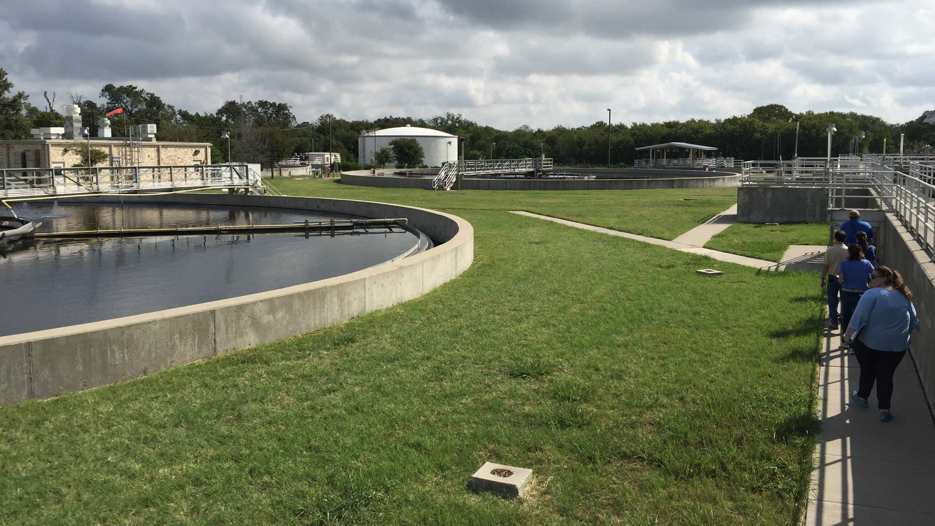
The Brushy Creek Regional Wastewater Treatment Facility East Plant is a regional wastewater treatment plant owned by the City of Round Rock, City of Cedar Park and City of Austin with the City of Leander becoming an owner in this expansion project. This project evaluated the expansion of the existing 21.5 million gallons per day (MGD) treatment facility to an ultimate average flow capacity of 40 MGD. Services provided included evaluation and subsequent design and construction phase services for the expansion.
Project Approach
KFA served as a subconsultant for this project, which expanded the Brushy Creek Regional Wastewater Treatment Facility East Plant from 21.5 MGD to 30 MGD, with a second planned expansion to the ultimate capacity of 40 MGD. KFA’s scope included influent flow projections; influent screening and grit removal evaluation; floodplain modeling and site improvements; influent flow splitting and pumping; yard piping and plant water design; and effluent UV disinfection, post aeration, and metering design:
- Influent flow projections: KFA reviewed historical flow data into the plant and rainfall data from nearby rain gauges to determine average dry weather, peak dry weather, and peak wet weather flows, as well as an appropriate peaking factor for the expansion. Population and flow projections were gathered from the partner cities to calculate flow projections to confirm that the expansion capacity was sufficient.
- Floodplain modeling: For the floodplain modeling, KFA reviewed a recently revised hydrologic model for the Upper Brushy Creek watershed to determine a revised 100-year floodplain elevation and the floodplain limits on the plant site using HEC-RAS. As the 100-year floodplain was higher than previous, KFA evaluated multiple options for protecting the site and process units from inundation in a 100-year flood. Each option was modeled and mitigation was evaluated to ensure that no impacts to the floodplain elevation were caused by any of the project improvements.
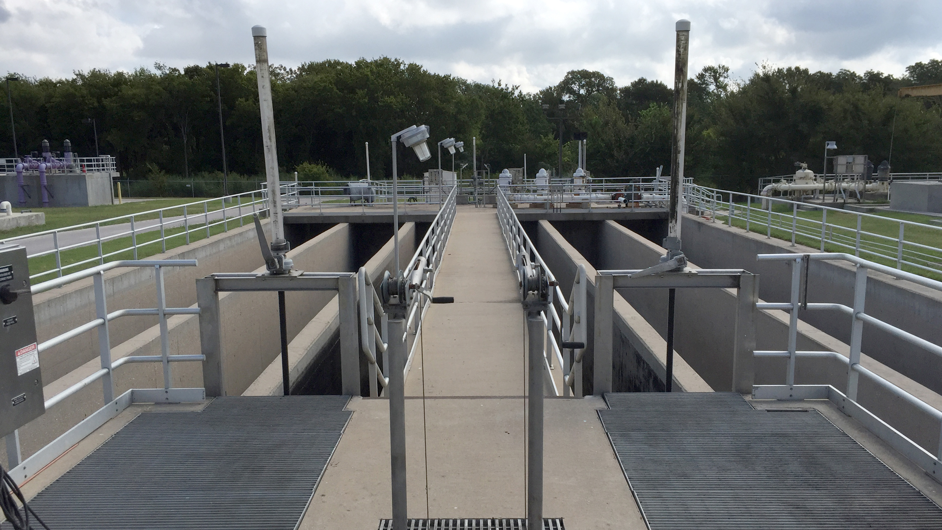
- Influent flow splitting: For the influent flow splitting task, KFA used the flow projections from the partner Cities to calculate the ultimate influent flow via three separate interceptors. These flows were used to determine the flow splitting requirements in order to evenly distribute the total influent to two on-site lift stations with equal pumping capacity.
- Headworks evaluation: For the headworks evaluation, KFA assessed multiple fine and coarse screen technologies, and grit removal technologies. KFA prepared a preliminary headworks layout that was used as the basis for final design.
During the final design phase, KFA was responsible for the following design elements:
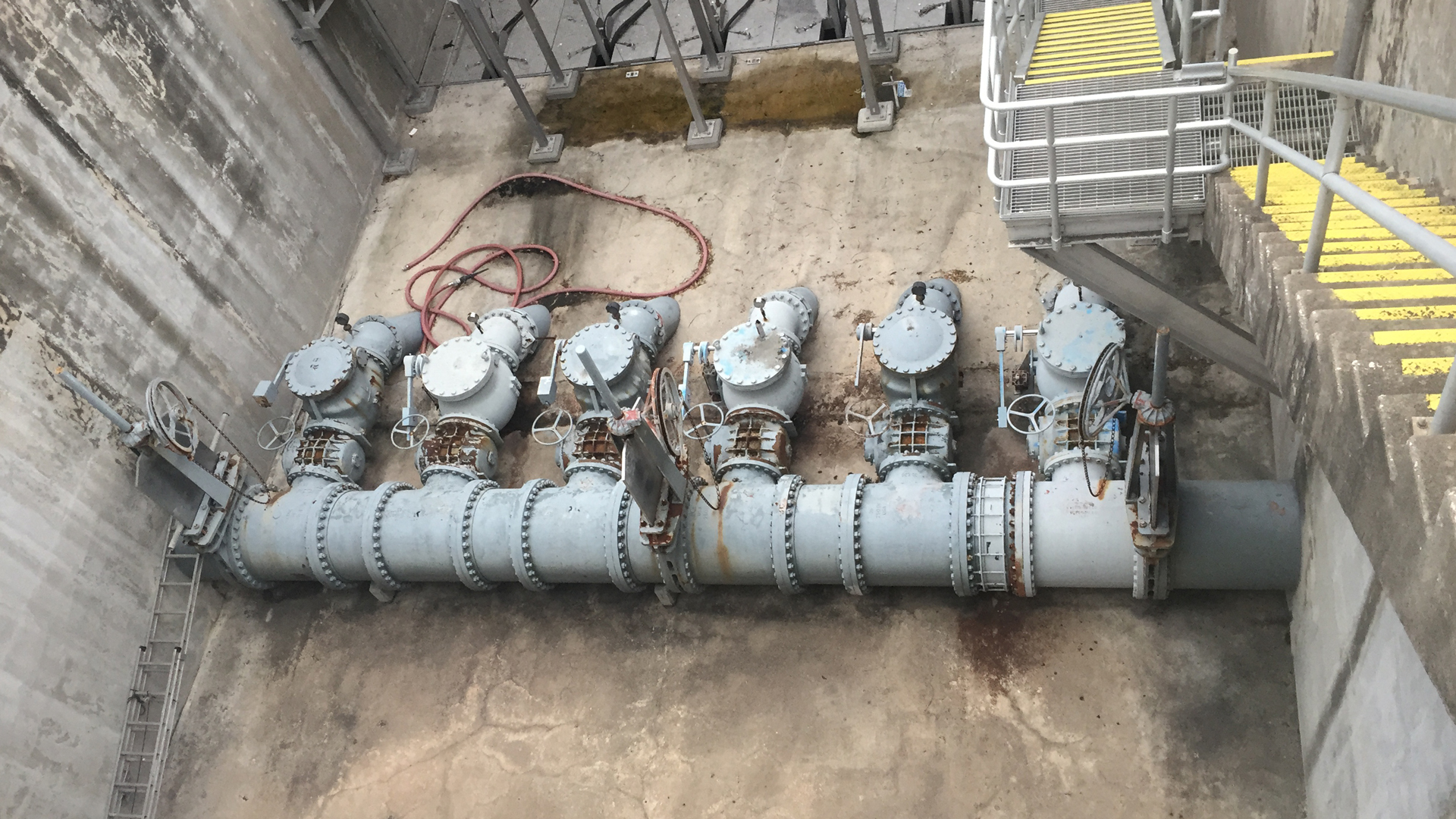
- New influent interceptor: Design of the 60-inch interceptor included a flow splitting manhole, bypass pumping design for influent flows up to 42 MGD, and a trenchless crossing at depths greater than 40 feet.
- On-site lift station: The new on-site lift station is roughly 45 feet deep. Design included an ultimate layout for five 200-horsepower submersible pumps (with three to be installed with this expansion), and a FOG (Fat, Oil & Grease) removal system to reduce lift station cleaning for the operators.
- Septage receiving station: The existing facility receives waste from septage haulers via an existing manhole located near the solids processing units and requires the haulers to drive through a portion of the plant site for entry and exit. KFA evaluated several septage receiving stations and developed a design located on the exterior of the plant, which allowed for future automated billing and septage screening and testing.
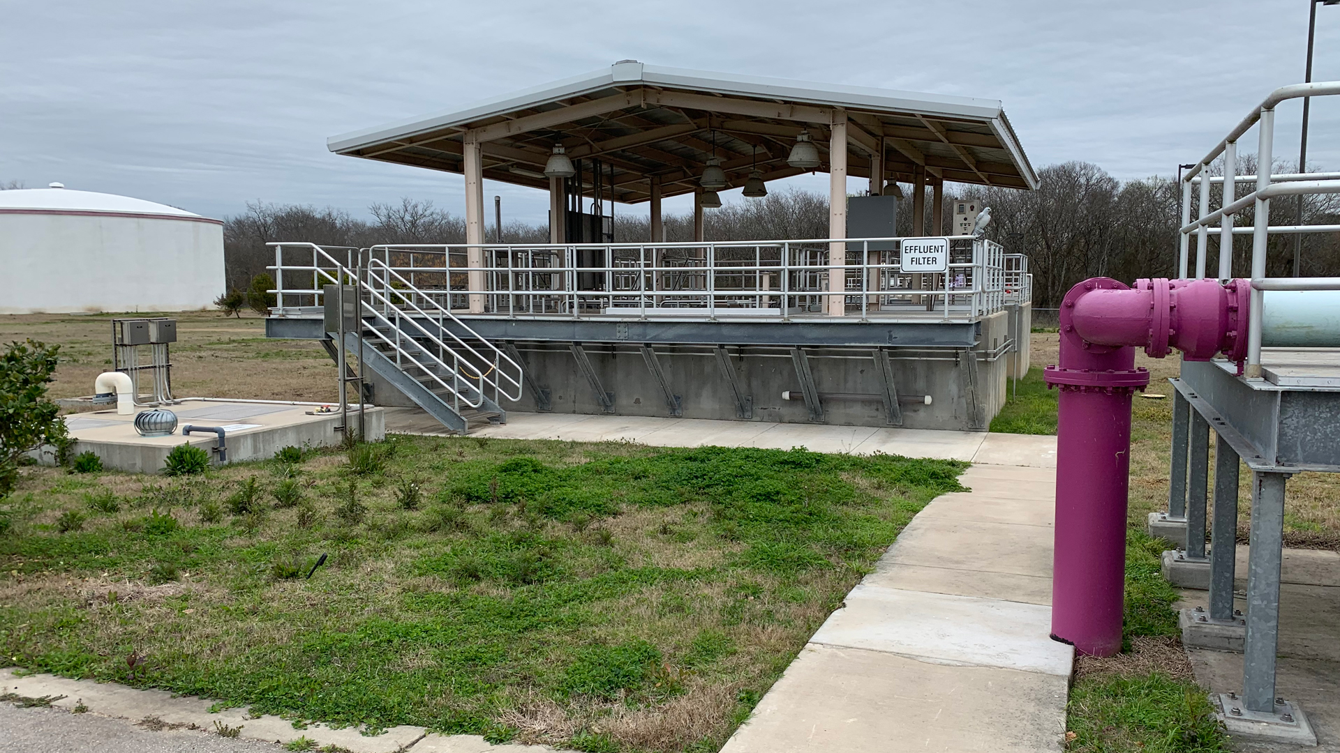
- UV disinfection system: For the new 60 MGD UV disinfection system, KFA evaluated several UV disinfection technologies and equipment configurations, and worked with manufacturers to calculate the UV dosing and equipment requirements to meet the permit limits.
- Fine bubble post aeration system: The new 60 MGD post aeration system includes removable fine bubble diffuser grids and positive displacement blowers to meet the dissolved oxygen requirements in the plant effluent.
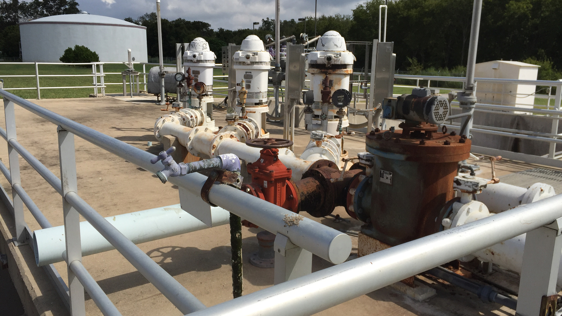
- Plant water system: KFA developed a hydraulic model of the existing plant water system to determine the available flow and pressure required to operate the various plant equipment that relied on reuse water. Ultimately, the existing City of Round Rock reuse system was tied into the plant water piping to provide the plant flows, and a separate pump was installed within the post aeration basic to serve the odor control system.
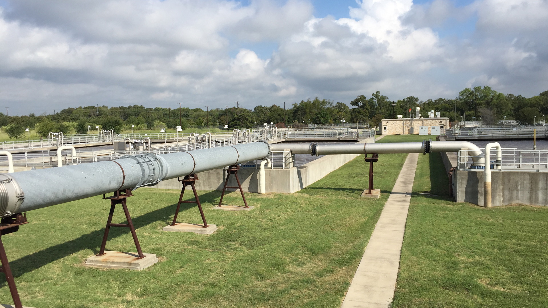
- Yard piping: For the yard piping design, KFA designed the horizontal and vertical alignments of more than 33,000 LF of 6-inch to 78-inch piping around the plant site. KFA evaluated as-builts, SUE data, and performed site visits to determine alignments of new piping to avoid impacting existing plant operations during the expansion construction.
- General site/civil design: KFA also designed the new plant driveways and the on-site storm water collection system, using HEC-RAS and StormCAD modeling.
Project Results
The project is currently in construction with KFA providing submittal and shop drawing reviews, RFI reviews and coordination, routine site visits, and start-up services.